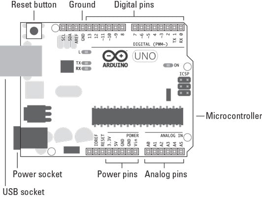

Here we are going to take the voltage provided at the OUTPUT terminal and feed it into one of ADC channels of Arduino. To filter out the noise capacitors are placed across output terminals as shown in figure. The two buttons here are for voltage increment and decrement. The display unit shows the voltage at the OUTPUT terminals.īefore going for working we need to look into ADC and PWM features of Arduino UNO. The voltage across output is not completely linear it will be a noisy one. The circuit for variable voltage unit using arduino is shown in below diagram. Software: Atmel studio 6.2 or AURDINO nightly. Hardware: Arduino Uno, Power supply (5v), 100uF capacitor (2 pieces), button (2 pieces), 1KΩ resistor (3 pieces), 16*2 characters LCD, 2N2222 transistor. The working and circuit is explained below.

With the display in place we can easily see the power fluctuations in the system. This variable power supply unit contains button interface for the voltage programming. This circuit output can also be used to charge AA or AAA rechargeable batteries. This circuit can provide currents up to 100mA, so we can use this power unit for most of the sensor modules without any trouble. So with this we may provide voltages accurately for the other modules. With this we cannot get a regulator for every one of them. So here we will make a simple circuit which will provide a voltage output from 0-5 volts at a resolution of 0.05V. Some digital electronic modules like accelerometer work on voltage 3.3V and some work on 2.2V. For that we are going use ADC (Analog to Digital Conversion) and PWM (Pulse Width Modulation) feature. In this tutorial we will develop a 5V variable voltage source from Arduino Uno.


 0 kommentar(er)
